Installation of Geomembrane
1.1 Civil Engineering Works
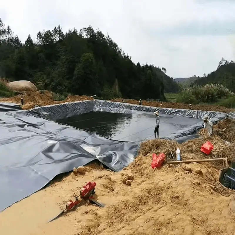
1.1.1 Preparation of the Surface
Based on the engineering plan, the civil engineering contractor shall be responsible for the following preparations.
The site supervisor will verify:
1) The lining surface should be prepared, free of any irregularities, protrusions, vegetation, excessive water, loose soil, or sudden changes in slope.
2) The supporting surface must not contain stones or other substances of similar composition, shape, or size that could damage the geomembrane.
3) There should not be excessive areas of soft surface.
Under any circumstances, installers must adhere to these rules when deploying any geomembrane. A complete surface acceptance form will be specially provided to the customer, indicating that this area has been accepted in the daily geomembrane installation activities. This form will be provided after the installation activities in the area. During the installation process of the geosynthetic lining system, if the surface layer is found to be deteriorated, damaged, or deemed unacceptable by the site supervisor at any time, the lining installation work in all these areas will be stopped, and relevant parties will be notified to take action.
1.1.2 Anchor Trenches
Anchor trenches for the lining are generally constructed by the civil engineering contractor, with depths and heights as indicated on the drawings and specifications. This task should be carried out prior to the installation work on the ground.
The ends of the geosynthetic material placed in the trench should not have irregular protrusions to avoid potential damage. The backfilling of anchor trenches shall be the responsibility of the civil engineering contractor, as per the detailed specifications. Backfilling should be done when the geosynthetic material is in the most compliant state with the contract to avoid potential joint issues. Care should be taken during the backfilling process to avoid damaging the geosynthetic material.
1.2 Installation of Geomembrane
The site supervisor and the customer shall jointly agree on the following points. In case of any adverse conditions or disputes, the site supervisor shall halt the installation until the disputes are resolved.
1.2.1 Installation
The site supervisor shall deploy as follows:
l Installation equipment shall not damage the surface.
l Individuals in contact with the lining material shall not smoke, wear damaging footwear, or engage in other hazardous behaviors that may damage the lining material.
l Low-ground-pressure, rubber-tired ground vehicles shall be used on the surface of geosynthetic materials. Comprehensive protection measures shall be taken to avoid damage and excessive traffic.
The installation sequence of on-site sheets shall consider site drainage, wind direction, surface conditions, site roads, and the engineering plan. Installation of geomembrane sheets shall be stopped when adverse weather conditions exist that may compromise the integrity of the lining installation. On-site sheets shall be welded as soon as possible after installation, and all installed materials shall be clearly marked.
1.2.2 Visual Inspection
The site supervisor and/or quality assurance engineer, as well as independent design inspectors, shall visually inspect each membrane as soon as possible after installation to identify any damage or areas needing repair and mark them accordingly.
1.3 Field Welding
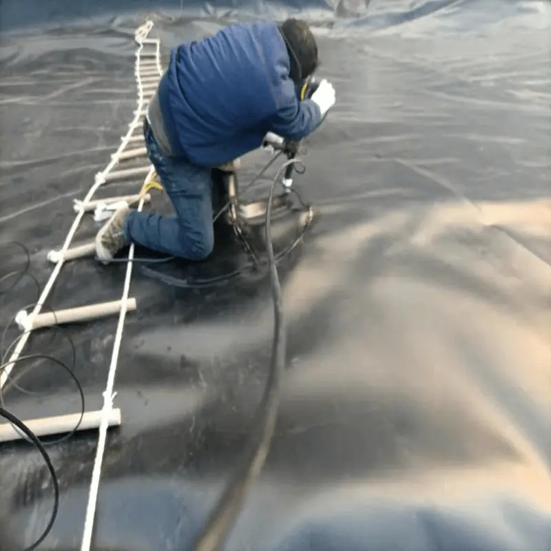
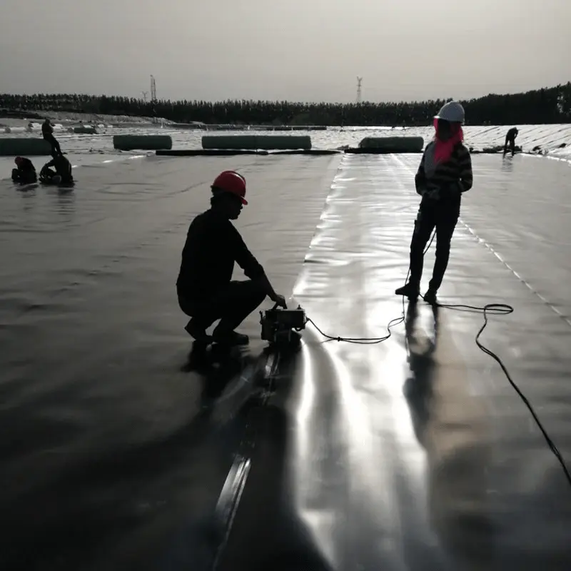
Field welding involves joining adjacent sections using a heating method.
1.3.1 Weld Design
Generally, welding aims to be parallel to the line of maximum slope, i.e., following the contour rather than crossing the slope. At corners and protrusions, the number of seams shall be minimized. Horizontal seams shall not occur within 1.5 meters from the slope base. This rule does not apply to slopes with a gradient less than 1:10. Cross-slope seams can be utilized if the ends are cut at an angle close to 45 degrees.
A numbering system using adjacent geomembrane sheet numbers is used to identify each seam.
1.3.2 Welding Equipment and Products
The methods used for field welding and repairs include extrusion welding and hot-melt welding. All welding equipment has precise temperature control devices to ensure accurate measurement of welding machine temperatures.
1) Fusion Method
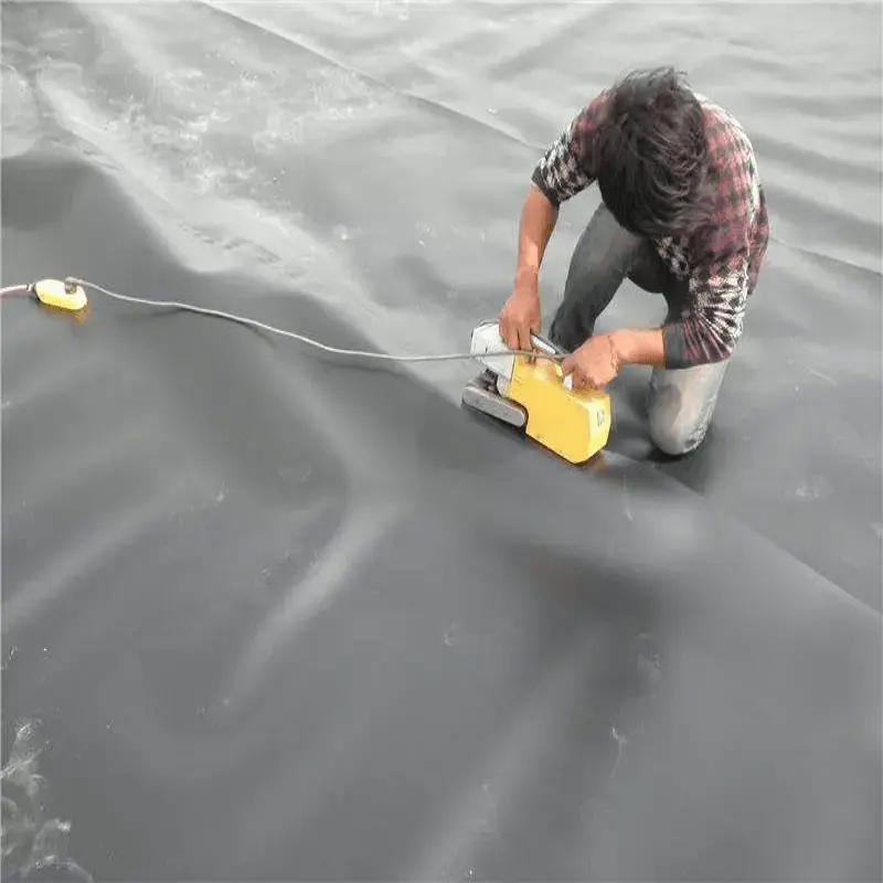
This method is typically used for welding entire rolls of sheet material and is not frequently employed for repairs or detailed work. The equipment features a hot tip, often equipped with a "split wedge" for air pressure welding tests.
Hot-melt welding machines are self-propelled and equipped with wedge temperature and welding speed controllers to ensure complete control by the welding engineer.
2) Extrusion Method
This method is primarily used for repairs, patching, and detailed assemblies. It is also suitable for connecting new sheets to previously installed liners that cannot undergo hot-melt welding due to the absence of protruding ends.
Extrusion welding equipment is equipped with temperature control devices.
1.3.3 Welding Preparation
The welding engineer shall conduct inspections before welding. The welding area should be free of moisture, dust, dirt, sand, gravel, or any other natural debris. The seams should be fully overlapped during welding. For extrusion welding, the weld seam should be preheated, fixed, and its surface ground to minimize the occurrence of "fish mouth" defects.
1.3.4 Testing Seams
Before welding, the seam should first be tested using engineering specifications and criteria. Each seam sample should be numbered, and test results should be recorded in a dedicated logbook.
l Operators of each welding machine and the primary operator of hot-melt welding machines shall conduct seam tests.
l Seam tests should be conducted before each welding session, typically at the start of each day and after lunch breaks.
l Hot-melt seam test samples should be approximately 2 meters long and 0.3 meters wide, with a longitudinal seam in the center. Extrusion seam test samples should be about 1 meter long and 0.3 meters wide, with a longitudinal seam in the center.
l Four samples, each 0.3 meters long and 0.15 meters wide, should be cut from the test seam using cutting tools. Two samples will undergo shear testing, and the other two will undergo peel testing. Both tests are conducted on-site using tensile testers. When testing hot-melt seams, both the inside and outside surfaces of the seam should be tested. All shear and peel test samples should meet engineering requirements.
1.3.5 Destructive Testing
All seams must undergo both non-destructive and destructive testing. Each tested seam should be labeled with relevant information.
1.3.6 Non-Destructive Testing
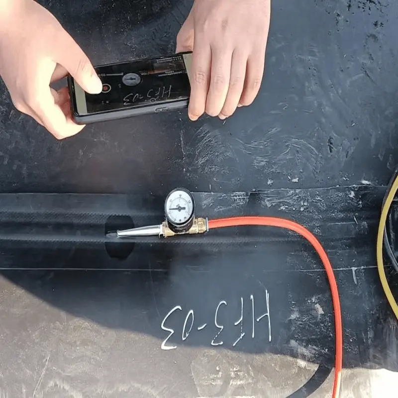
Seams are tested for maximum holding capacity using either pneumatic or vacuum testing methods. The purpose of non-destructive testing is to demonstrate the durability of the seams.
For seams that cannot undergo pneumatic or vacuum testing due to physical constraints, such as seams on boots, alternative testing methods should be employed.
The site supervisor should schedule non-destructive testing to ensure the quality and progress of the project.
QA technicians should educate testers on maintenance, leakage, and sealing knowledge.
1) Vacuum Testing
Vacuum testing is commonly used for extrusion welding or hot-melt welding. The equipment required includes a vacuum box (with a vacuum gauge), a charging device, and soap solution.
Follow these steps:
l Wet a section of the seam with soap solution, ensuring that the seam section is longer than the vacuum box.
l Place the vacuum box over the wet section and press firmly to create a seal between the gasket and the liner.
l Evacuate the air to create a pressure difference of approximately 5KPa.
l Observe the seam through the viewing window for any soap bubbles emerging from the seam.
l If no soap bubbles are observed, move the vacuum box to the other wet section, with slight overlap, for the next test.
l If soap bubbles are seen, it indicates a leak in the seam. Mark the leak for repair and retesting.
2) Pneumatic Testing
Pneumatic testing uses a double-layered seam hot-melt welding equipment to test seams.
The equipment consists of the following parts:
l An air pump or compressed air tank capable of generating a minimum of 2.5 MPa air pressure in the seam channel
l A pointed, hollow needle to allow air to enter the seam's air channel
l A hot air gun or other heating device to seal the ends of the air channel
Follow these steps:
l Seal both ends of the seam's air channel for testing
l Insert the needle into the air chamber from either end of the seam for testing
l Pressurize the air channel to 3 MPa and maintain a stable pressure. If necessary, adjust the pressure to 2.5 MPa and observe the pressure
l Maintain the air pressure in the air channel at a minimum of 2.5 MPa
l Observe the pressure again after approximately 5 minutes
l If the pressure difference exceeds 0.5 MPa between the two observations, the seam needs to be retested
l Upon completion of the test, record all required information, then open the port opposite the needle entry. The escaping air confirms the maximum holding capacity of the pressurized seam. If no air leaks out, the channel is blocked. Record the blockage and retest starting from that point
l After completing the pneumatic test, mark the seams and areas requiring repair
3) Steps After Failed Air Testing:
In the case of failed joint sealing during air testing, the following steps should be taken:
l Reposition the instrument and conduct retesting on the same section.
l Place the joint air channel under pressure and test for leaks across the joint.
l Apply soap solution to the ends of the joint while it is under pressure and observe for bubbles indicating air leakage.
l Gradually increase the retesting volume in small increments until the leak is located.
l Perform extrusion welding on the leak using excess material from the joint and conduct a vacuum test.
l The vacuum test can only be accepted when the air channel is sealed and the integrity of the welding is not in doubt.
1.3.7 Destructive Joint Testing
Destructive joint testing should be conducted at selected locations to measure the bond seam strength. The testing should be carried out step by step.
1) Location and Frequency
The sampling frequency is generally one sample per 150 meters of continuous joint.
2) Sample Size
A 0.3m x 0.3m sample slice will be cut from the sample with the joint as the longitudinal center, and additional slices may be cut for independent laboratory testing, archiving, or other purposes.
3) Sample Identification
The slices should be labeled with appropriate destructive specimen (D/S) numbers.
4) Area Testing
Test the surface and shear strength of the samples according to the following steps:
l Cut 10 one-inch-wide samples from the slice using a mechanical press and punch.
l Measure the surface strength of 5 samples, testing the hot-melt weld from both sides.
l Measure the shear strength of the other 5 samples.
l If specified, a tensile tester should be provided. The test should be conducted at a rate of 2 inches per second.
1.3.8 Defects and Repairs
All impermeable membrane joints and non-joint areas will be inspected for defects. Defects should be identified and repaired using appropriate marking tools in the joint area.
1) Repair Steps
Any imperfections in a polyethylene lining system can be addressed using one or more of the following methods simultaneously.
l Patching. Suitable for holes and tears.
l Grinding and welding. Suitable for repairing small sections of molded seams.
l Spot welding. Suitable for repairing small, localized defects.
l Capping. Suitable for repairing failed seams.
l Overlaying. Providing an extruded sheet directly over the existing seam.
The identified imperfections will reveal the damage and characteristics of the lining material.
The above methods require the following conditions:
l The polyethylene surface to be repaired should be lightly grinded to ensure cleanliness.
l All surfaces that will receive extrusions must be cleaned and dried during the repair process.
l All patches and overlays should extend at least 10cm above the edge of the defect, and all patches should have rounded corners.
2) Repair Verification
The repair should undergo non-destructive testing according to section 1.3.6.
A repair that passes the non-destructive test will serve as evidence of adequate repair. If the test fails, the repair must be redone until it passes the test.
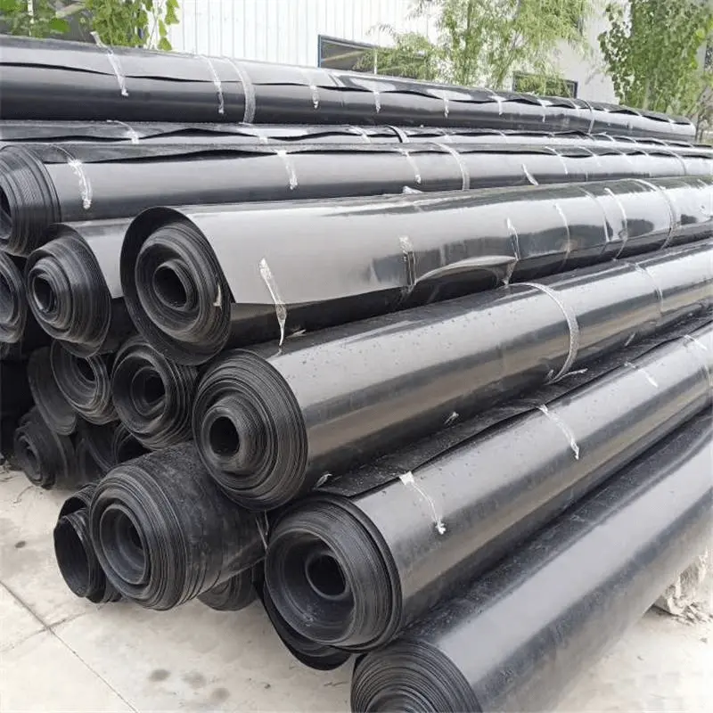
Haoyang Environmental specializes in the production and wholesale of various specifications of geomembranes, catering to a wide range of applications such as landfills, reservoirs, and containment systems. Our geomembranes are made from high-quality materials, ensuring durability, impermeability, and resistance to environmental stresses. We are committed to providing innovative solutions that meet the diverse needs of our clients worldwide. With a focus on quality and competitive pricing, we welcome customers from all countries to inquire about our products and place orders. Partner with Haoyang Environmental for reliable geomembrane solutions that ensure the success of your projects!
![]() 0.5 Double-sided smooth HDPE geomembrane.pdf
0.5 Double-sided smooth HDPE geomembrane.pdf
897.webp)
942.webp)
237.webp)