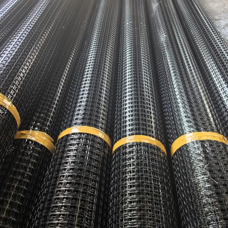
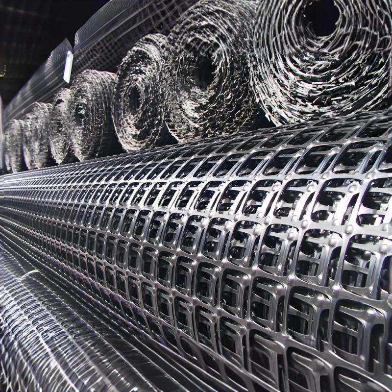
1.What’s fiberglass geogrid?
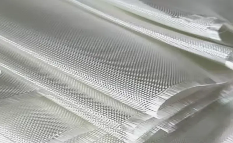
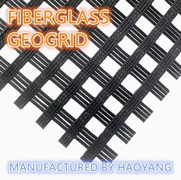
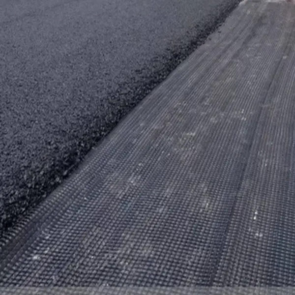
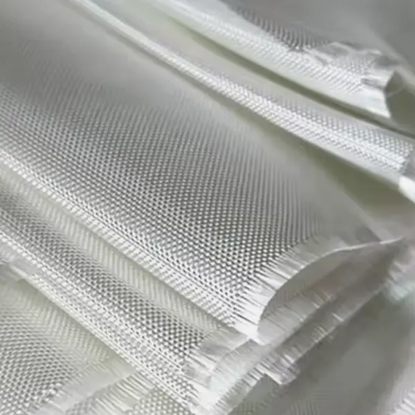
Fiberglass geogrid is an excellent geosynthetic material used for pavement reinforcement, old road reinforcement, roadbed reinforcement and soft soil foundation reinforcement. Fiberglass geogrid is a semi-rigid product made of high-strength alkali-free glass fiber through the internationally advanced warp knitting process into a mesh substrate and surface coating. It has high tensile strength and low elongation in both warp and weft directions, and has excellent properties such as high temperature resistance, low cold resistance, aging resistance, and corrosion resistance. It is widely used in asphalt pavement, cement pavement and roadbed reinforcement, railway roadbed, dam slope protection, airport runway, sand control and other engineering projects.
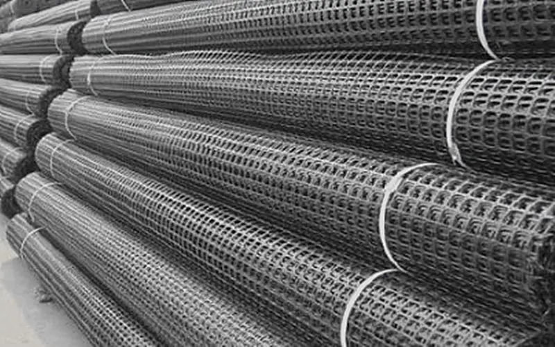
2. Principle of fiberglass geogrid
2.1. Reducing reflective cracks
Reflective cracks are caused by stress concentration in the asphalt overlay layer above the old concrete surface layer due to the large displacement near the joints or cracks. It includes horizontal displacement caused by temperature and humidity changes, and vertical shear displacement caused by traffic loads. The former causes concentrated tensile stress in the asphalt overlay above the joint or crack; the latter causes the asphalt overlay above the joint to be subjected to greater bending tensile stress and shear stress.
Since the modulus of geogrid is very large, reaching 67Gpa, it is used as a hard interlayer with high rigidity in the asphalt overlay. Its function is to suppress stress and release strain. At the same time, as an asphalt concrete reinforcement material, it improves the tensile and shear resistance of the overlay structure, thereby achieving the purpose of reducing cracks. Practice shows that the corresponding crack energy of a horizontal crack that has changed direction can move 0.6 meters from its starting point. Reinforcement materials with a width of more than 1.5 meters help ensure that the energy is completely dissipated on both sides of the crack.
2.2. Anti-fatigue cracking
The main function of the asphalt overlay on the old cement concrete pavement is to improve the use function of the pavement, but it does not contribute much to the bearing function. The rigid concrete pavement under the overlay still plays a key bearing role. However, it is different when the asphalt overlay is applied on the old asphalt concrete pavement. The asphalt overlay will bear the load together with the old asphalt concrete pavement. Therefore, when asphalt overlay is applied on asphalt concrete pavement, in addition to reflective cracks, fatigue cracking will also occur due to the long-term effect of load. We conducted a stress analysis on the load of the asphalt overlay layer on the old asphalt concrete pavement: Since the asphalt overlay layer is a flexible surface layer with the same properties as the asphalt overlay layer, the road surface will bend when subjected to load. The asphalt overlay layer in direct contact with the wheel is subjected to pressure, and the surface layer is subjected to tension in the area outside the wheel load edge. Since the forces in the two stress areas are different in nature and close to each other, damage is easily caused at the junction of the two stress areas, that is, the point where the forces suddenly change. Fatigue cracking occurs under the action of long-term load.
In the asphalt overlay layer, the glass fiber geogrid can disperse the above-mentioned compressive stress and tensile stress, forming a buffer zone between the two stress areas, where the stress changes gradually instead of suddenly, reducing the damage to the asphalt overlay layer caused by sudden stress changes. At the same time, the low elongation of the glass fiber geogrid reduces the deflection of the road surface, ensuring that the road surface will not undergo transitional deformation.
2.3. High temperature rutting resistance
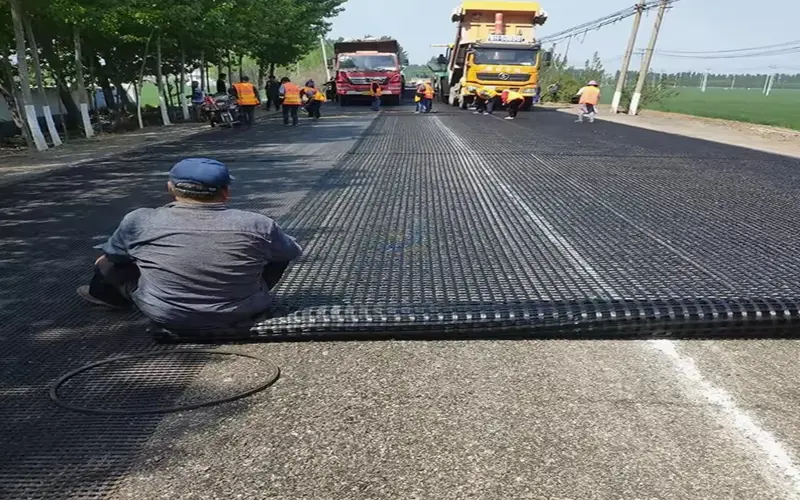
Asphalt concrete has rheological properties at high temperatures, which are specifically manifested in: the asphalt road surface becomes soft and sticky in summer; under the action of vehicle load, the stress area is sunken, and the asphalt surface cannot be completely restored to the state before the load after the vehicle load is removed, that is, plastic deformation occurs; under the repeated rolling of vehicles, plastic deformation continues to accumulate, forming rutting. After analyzing the structure of the asphalt surface layer, we can know that due to the rheological properties of asphalt concrete at high temperatures, when subjected to load, there is no mechanism in the surface layer that can constrain the movement of aggregates in the asphalt concrete, causing the asphalt surface layer to move, which is the main reason for the formation of rutting.
Glass fiber geogrids are used in the asphalt overlay layer, which plays a skeleton role in the asphalt surface layer. Aggregates in asphalt concrete run through the grids to form a composite mechanical interlocking system, which restricts aggregate movement and increases the lateral constraint force in the asphalt overlay layer. The various parts of the asphalt surface layer restrain each other, preventing the asphalt surface layer from moving, thereby playing a role in resisting rutting.
2.4. Resistance to low temperature shrinkage cracking
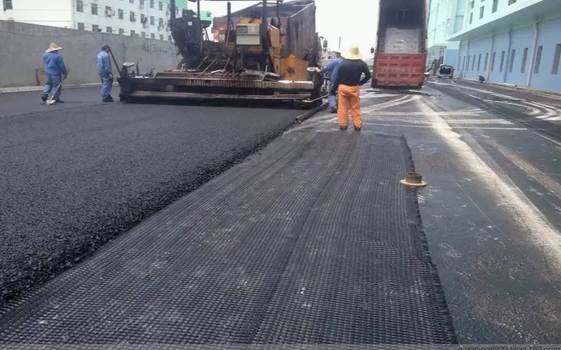
For asphalt roads in cold areas, the surface temperature in winter is close to the air temperature. Under such temperature conditions, asphalt concrete shrinks when it is cold, generating tensile stress. When the tensile stress exceeds the tensile strength of asphalt concrete, cracks are generated, and cracks are generated in places where cracks are concentrated, forming diseases. From the cause of the cracks, how to make the strength of asphalt concrete resist tensile stress is the key to solving the problem.
The application of glass fiber geogrid in asphalt overlay greatly improves the tensile strength of asphalt concrete, which can resist large tensile stress without damage. In addition, even if cracks occur in local areas, the stress at the crack site is too concentrated, but it gradually disappears through the transmission of glass fiber geogrid, and the crack will no longer develop into a crack. When selecting fiberglass geogrid, in addition to its performance indicators meeting the requirements of the above table, special attention should be paid to ensuring that its width is not less than 1.5m, so that it has sufficient cross-sectional area to fully dissipate crack energy when used as a control layer for reflective cracks; at the same time, its mesh size should be 0.5~1.0 times the maximum particle size of the asphalt surface material above it, which helps to achieve the best shear adhesion and promote aggregate interlocking and restriction.
3. Main uses of fiberglass geogrid:
3.1. Old asphalt concrete pavement, reinforce the asphalt surface layer, and prevent and control diseases.
3.2. Reconstruction of cement concrete pavement into composite pavement to inhibit reflective cracks caused by plate shrinkage.
3.3. Road expansion and modification projects to prevent cracks caused by new and old joints and uneven settlement.
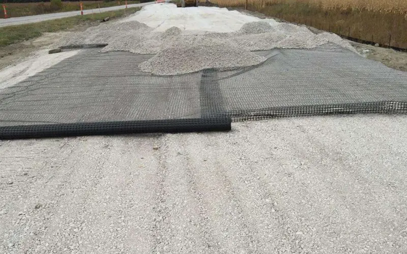
3.4. Reinforcement treatment of soft soil foundation is conducive to water separation and consolidation of soft soil, effectively inhibits settlement, evenly distributes stress, and enhances the overall strength of the roadbed.
3.5. Shrinkage cracks occur in the semi-rigid base of the newly built road, and reinforcement is used to prevent cracks in the road surface caused by reflection of the foundation cracks.
4. Classification and construction methods
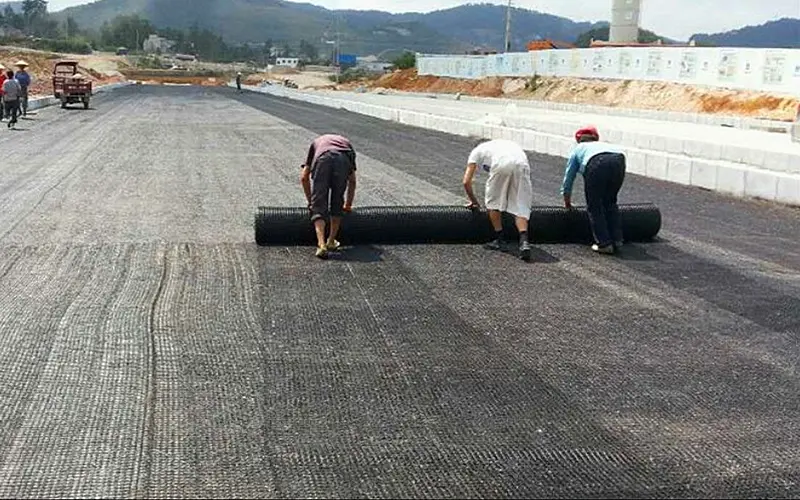
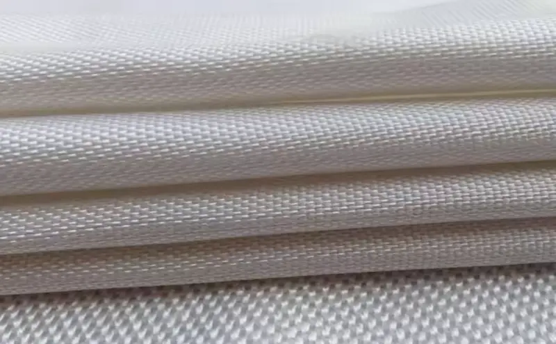
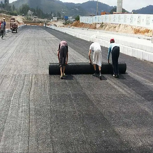
The commonly used fiberglass geogrids are with self-adhesive and without self-adhesive. The one with self-adhesive can be laid directly on the flat base, and the one without self-adhesive is usually fixed by nails.
4.1. Construction site: It is required to be compacted and flat, horizontal, and clear of sharp protrusions.
4.2. Laying of grids: On a flat and compacted site, the main force direction (longitudinal) of the installed grid should be perpendicular to the axis direction of the embankment, and the laying should be flat, without wrinkles, and as tight as possible. It is fixed with nails and soil and stone weight. The main force direction of the laid grid is preferably full-length without joints. The connection between the pieces can be manually tied and overlapped, and the overlap width is not less than 10cm. If the grid is set up in more than two layers, the layers should be staggered. After paving a large area, the straightness should be adjusted as a whole. After filling a layer of soil and before rolling, the grid should be tightened again by hand or machine, and the force should be uniform so that the grid is in a straight and stressed state in the soil.
4.3. Selection of filler: The filler should be selected according to the design requirements. Practice has shown that except frozen soil, swamp soil, domestic garbage, chalk soil, and diatomaceous earth, all can be used as fillers. However, gravel soil and sand soil have stable mechanical properties and are little affected by water content, so they should be used first. The particle size of the filler shall not be greater than 15cm, and attention should be paid to controlling the filler gradation to ensure the compaction weight.
4.4. Spreading and compacting of filler: After the grid is laid and positioned, it should be covered with soil in time, and the exposure time shall not exceed 48 hours. The flow operation method of laying and backfilling can also be adopted. First spread the filler at both ends, fix the grid, and then push it to the middle. The order of rolling is first the two sides and then the middle. The rollers cannot come into direct contact with the reinforcement during rolling. Vehicles are generally not allowed to drive on uncompacted reinforcements to prevent dislocation of the reinforcements. The layered compaction degree is 20-30cm. The compaction degree must meet the design requirements, which is also the key to the success or failure of reinforced soil engineering.
4.5. Drainage prevention measures: In reinforced soil engineering, drainage treatment inside and outside the wall must be done well; foot protection must be done to prevent erosion; filtration and drainage measures must be set up in the soil body, and geotextiles should be set up if necessary.
5.Technical parameters of fiberglass geogrids:
Specifications | Breaking strength(Kn/m) | Elongation at break(%) | Width(m) | ||
Radial | Latitude | Radial | Latitude | ||
HY-30 | ≧30 | ≧30 | ≦4 | ≦4 | 1~6 |
HY-40 | ≧40 | ≧40 | ≦4 | ≦4 | 1~6 |
HY-50 | ≧50 | ≧50 | ≦4 | ≦4 | 1~6 |
HY-80 | ≧80 | ≧80 | ≦4 | ≦4 | 1~6 |
HY-100 | ≧100 | ≧100 | ≦4 | ≦4 | 1~6 |
Haoyang Environmental Co., Ltd. is a company specializing in the production of geotechnical materials. It has more than 20 years of production experience and can provide free advice for any problems you encounter during the purchase and use of geotechnical materials. You can communicate with us at any time if you have any questions.
Email: sale2@hygeosynthetics.com
Monile: +8616615773081
503.webp)
759.webp)
